| Informational Websites | ChronoMaddox -- the legacy of Chuck Maddox | OnTheDash -- vintage Heuer website | Zowie -- Omega information |
| Discussion Forums | ChronoMaddox Forum | Heuer Forum | Omega Forum |
| Counterfeit Watchers | ChronoTools Forum | ChronoTrader Forum |
|
|
The largest independent, non-commercial, consumer-oriented resource on the Internet for owners, collectors and enthusiasts of fine wristwatches. Online since 1998. | |||||||
|
||||||||
|
||||||||
Vintage Heuer Discussion Forum
The place for discussing 1930-1985 Heuer wristwatches, chronographs and dash-mounted timepieces. Online since May 2003. | |||||||
| |||||||
| |||||||
Hi all,
Taking advantage of the Xmas holidays I thought to prepare this post, that is the ideal prosecution of the two previous posts about “How to disassemble a Chronomatic movement”:
http://chronocentric.com/forums/heuer/index.cgi?md=read;id=79646
and “How to clean a Chronomatic movement (part 2)” (quite trivial and generic and valid for all types of movements):
http://chronocentric.com/forums/heuer/index.cgi?md=read;id=79689
In the first post we saw that usually is not necessary to disassemble the chrono module to service it (this is also stated into the service manual, see pag.14), you can put it directly into the ultrasonic bath and, after having carefully dried it (to avoid the trapped water may rusts some parts) you will only need to dismount the two bridges and eventually a couple of screws to reach some points to be oiled (as we will see in this post).
However this time we will see how to reassemble, step by step, the chrono module just for sake of information (can happen you have to partially dismount it, e.g. to replace some broken / rusted parts) and to ideally conclude the first post, so will see in details all the steps described in the following four pages of the service manual (you can find it on OTD too or on the Chuck Maddox website):
I will only make three important assumptions, that are:
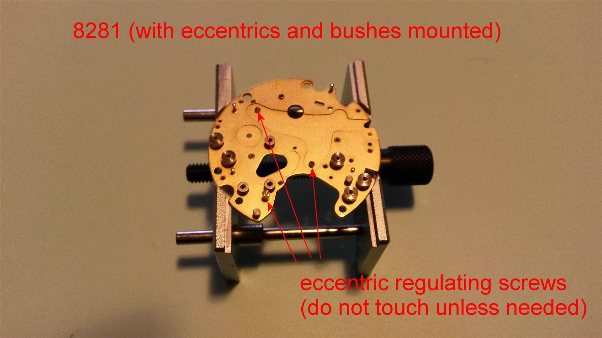
a) the chronograph module, before servicing, is working well and doesn’t need any regulation: in fact, into this module, there are some eccentric screws that is essential NOT to touch unless you need it (e.g to regulate the penetration of the oscillating pinion 8086 into the central chrono wheel 8000), otherwise you risk to deregulate one or more of the functions of the chronograph.
b) we will not explain the techniques involved in the art of oiling a watch (this would deserve an apposite post) so I will make the assumption that the reader knows how to oil / grease a watch and the differences involved among the various oils and greases needed.
c) All the parts of the chronograph module have already been dismounted and cleaned, so we are ready to reassemble it. Banally to dismount it you can follow the following steps bottom-up, obviously avoiding the oiling notes :-).
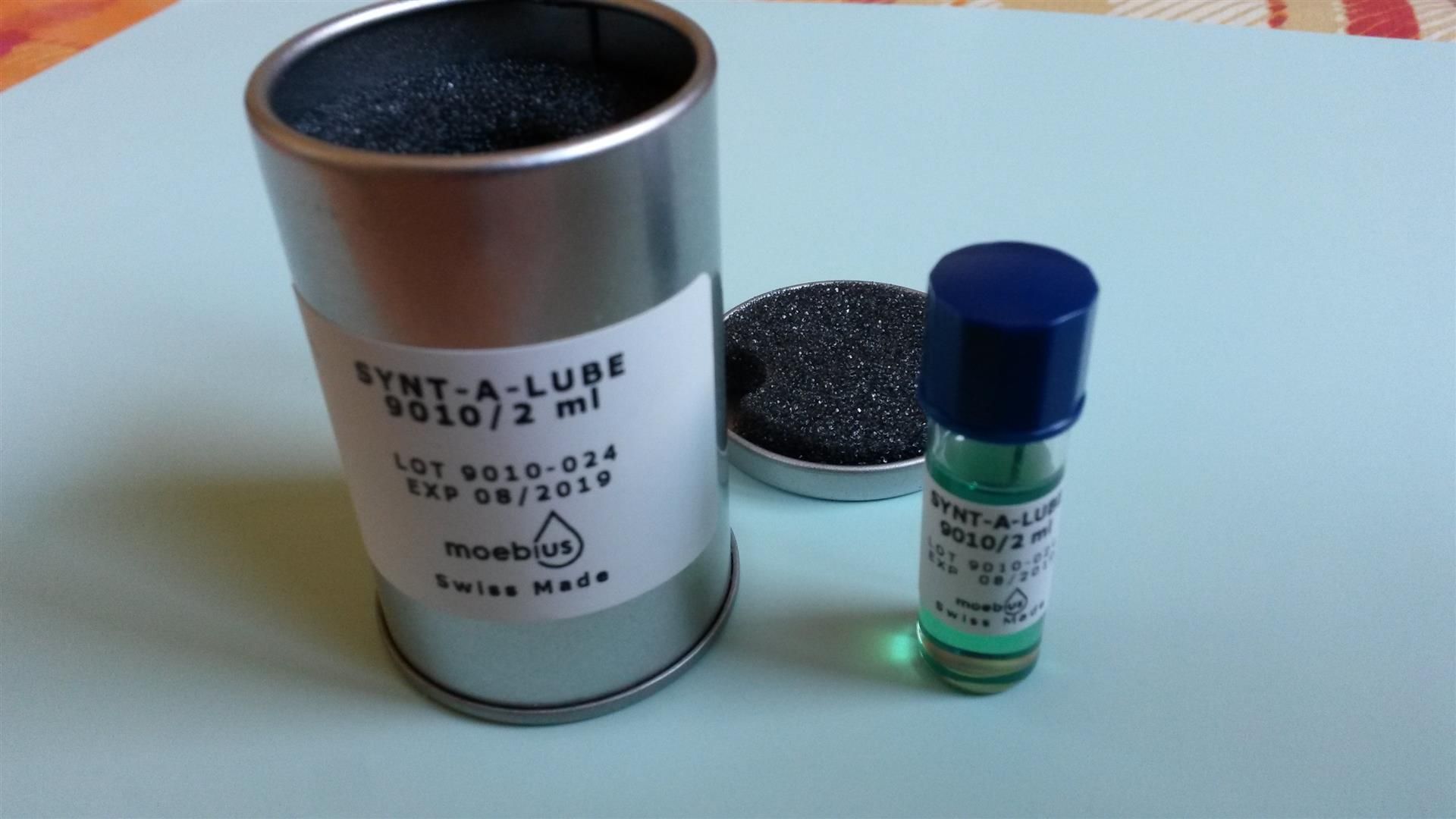
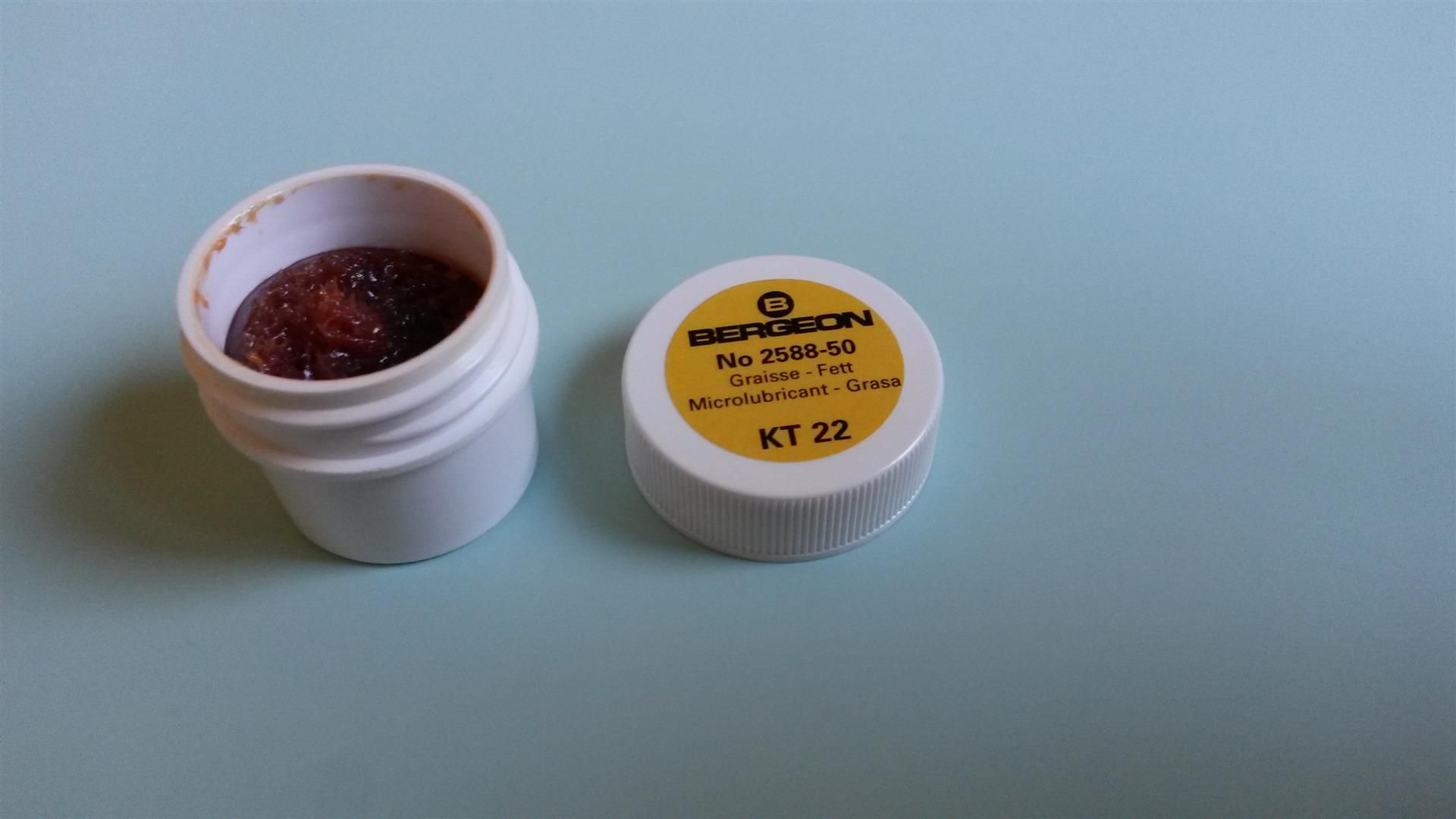
To service the chronograph module (its code is 8510 if fully mounted or 8281 for the base plate) only two lubricants are needed:
a) Synt-a-Lube: this is a thin oil, suitable for the pivot holes of “fast moving” wheels (e.g. the balance wheel’s jewels 324 and 325 of the main module, the oscillating pinion 8086) or wheels with very low pressure (all the chronograph module’s ones). I use the Moebius 9010.
b) Bergeon KT22: this is a grease (not an oil) and is used in the manual winding mechanism (here the wheels haven’t shafts but are similar to washers, so have a large surface to be lubricated but are relatively slow with an high load to sustain to wind the mainspring), in the setting mechanism, and in many points of the chronograph module where parts rubs one each other. I use the Bergeon KT22 but Moebius 8200 should be the same.
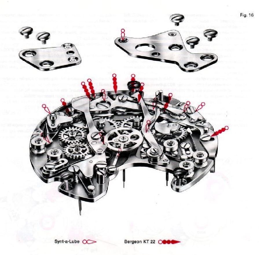
The following image is taken from the service manual and illustrate the “lubrication plan” of the chronograph module (that is “which oil or grease to put where”).
Obviously the oil or grease must be applied during the reassembling process of the parts in the points specified into the image.
Let’s start.
This is the naked 8281 chronograph plate, already fitted with bushes and regulating screws (into the Cal12/14/15 the latter are usually gold coloured while into the Cal11/11i are nickel coloured but there are some Cal12 with nickel coloured eccentrics too):
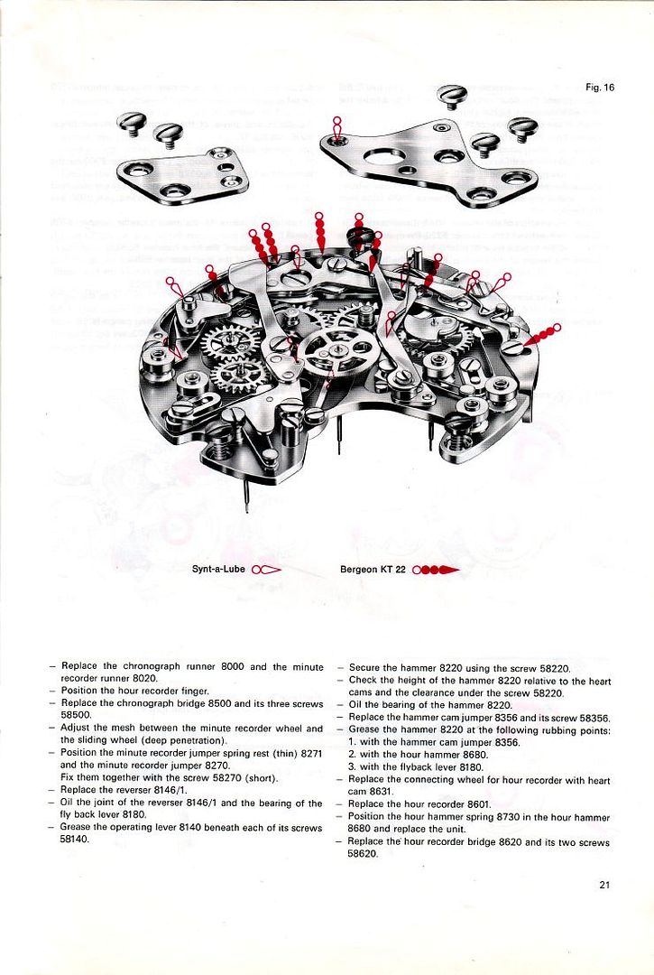
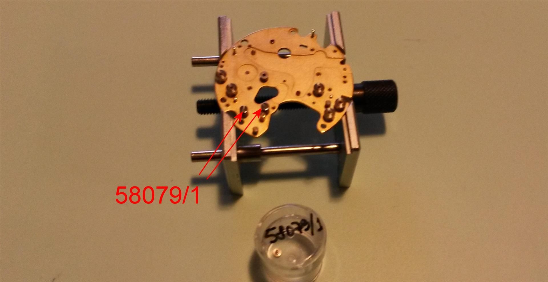
1) Replace the two coupling clutch screws 58079/1:
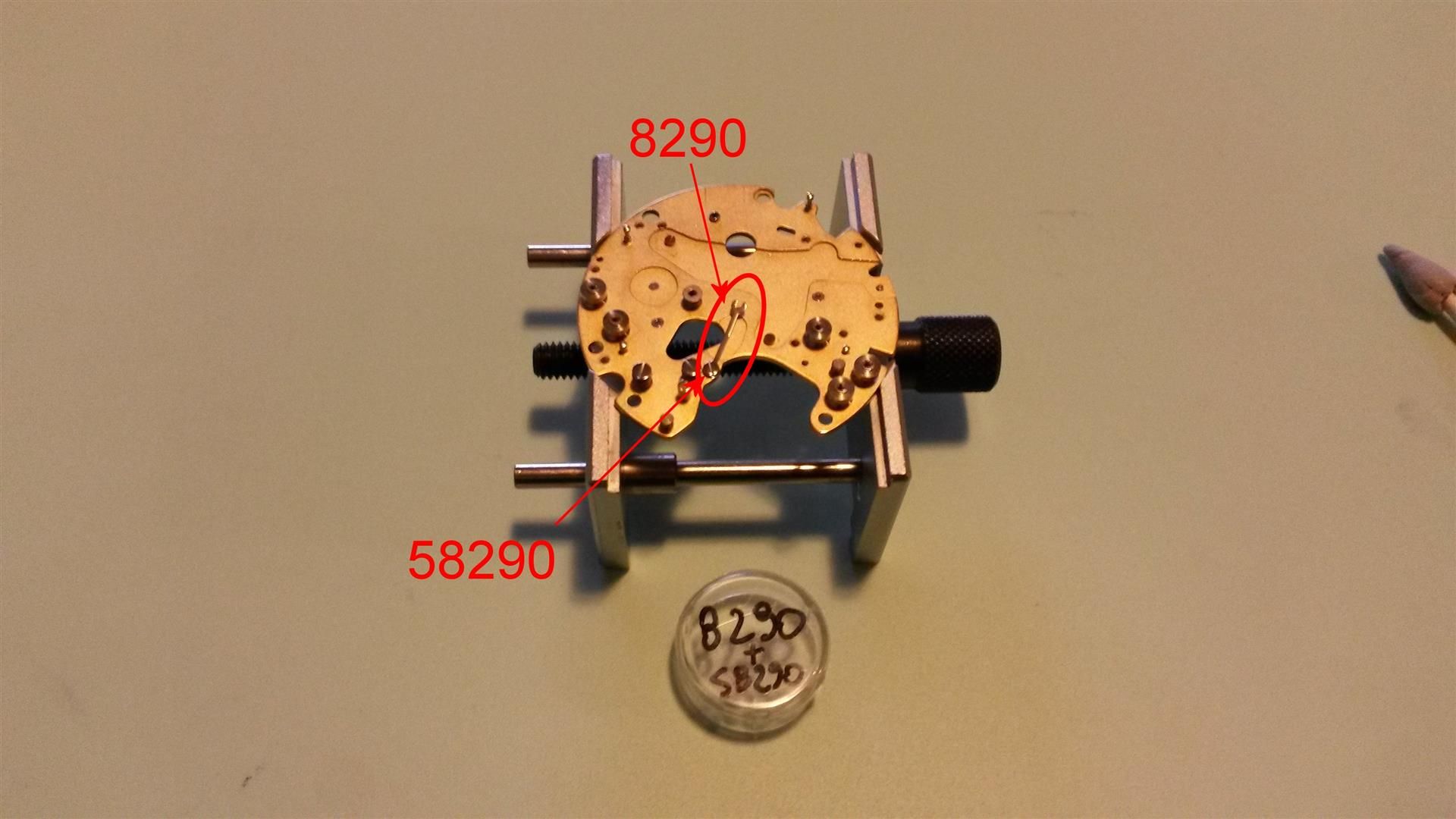
2) Secure the friction spring 8290 using its screw 58290:
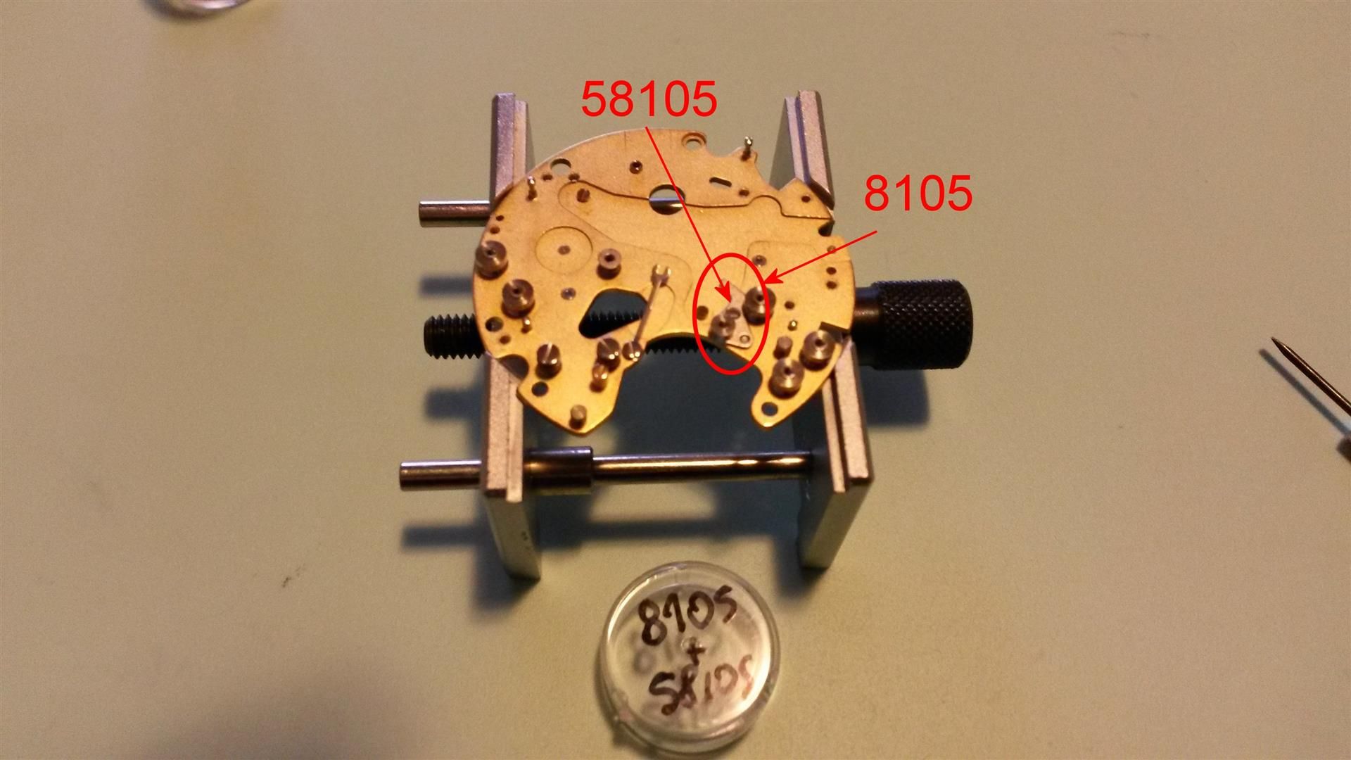
3) Replace the sliding gear bridge 8105 and secure it with the screw 58105:
4) Replace the sliding gear 8100 and secure it with its sliding gear screw 58100:

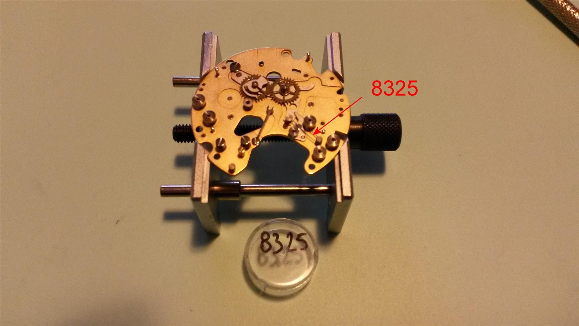
5) Replace the sliding gear spring 8325:
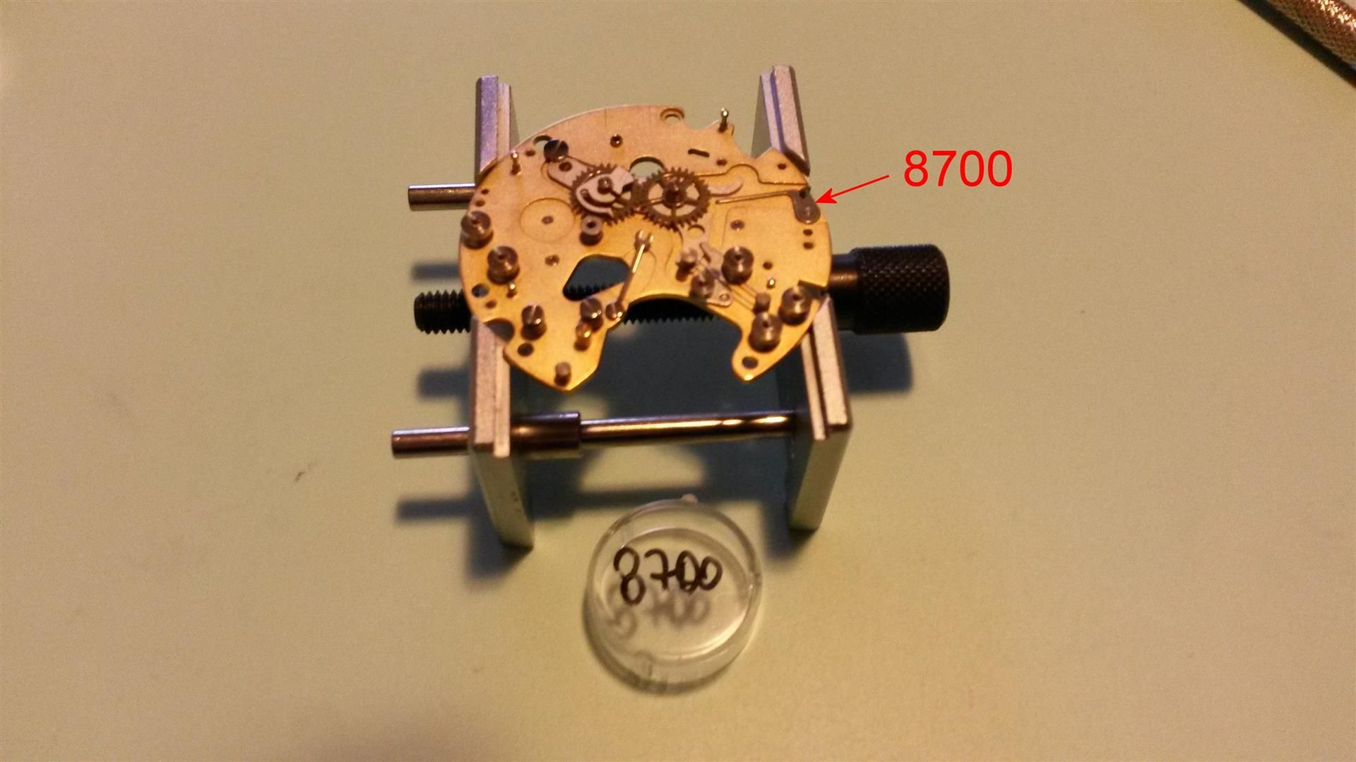
6) Replace the connecting plate 8700:
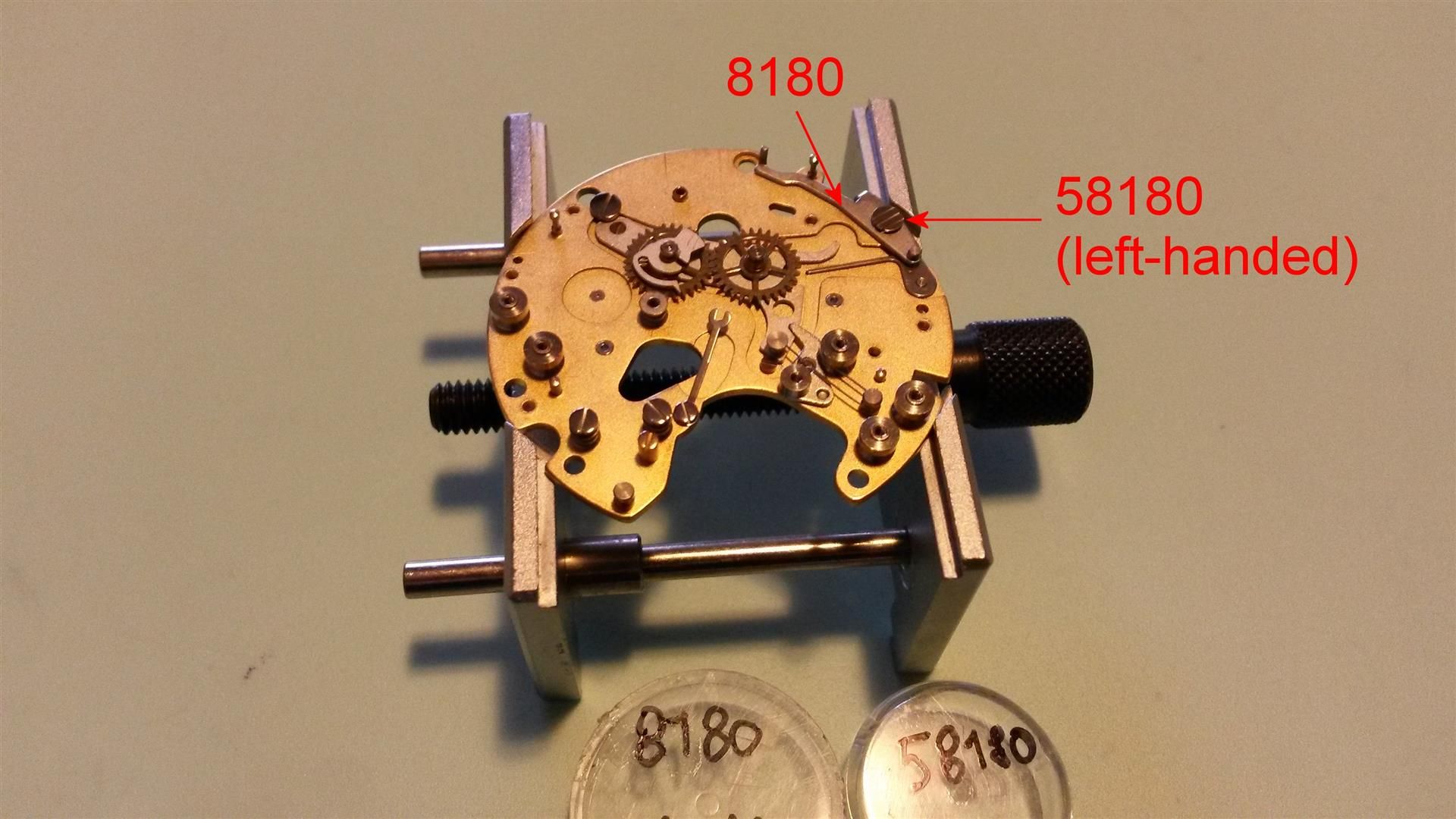
7) Secure the operating and fly-back lever 8180 with the screw 58180 (take care: is a left-hand screw!!!):
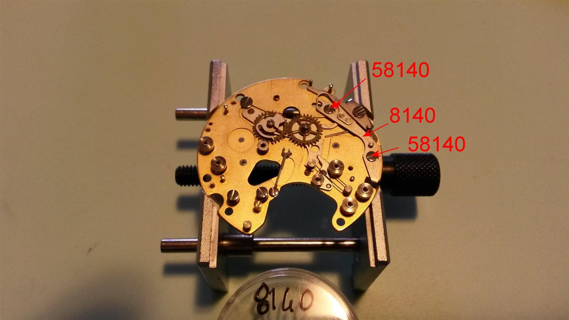
8) Replace the operating lever 8140 and its two screws 58140:
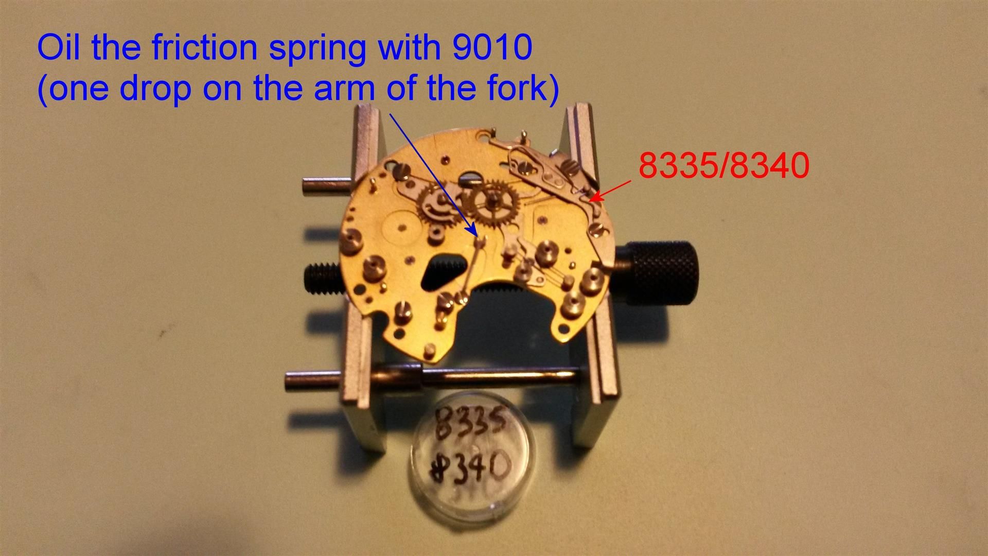
9) Replace the fly-back lever spring 8335/8340, then oil with Moebius 9010 the friction spring (one drop on the arm of the fork):
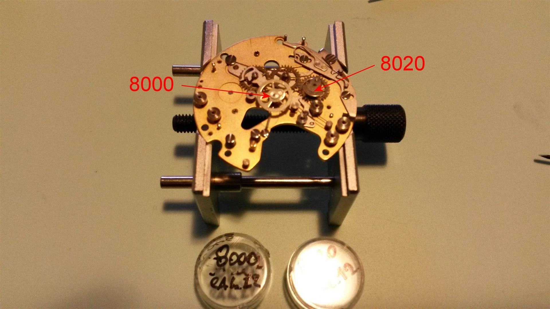
10) Replace the chronograph runner 8000 and the minute recording runner 8020:
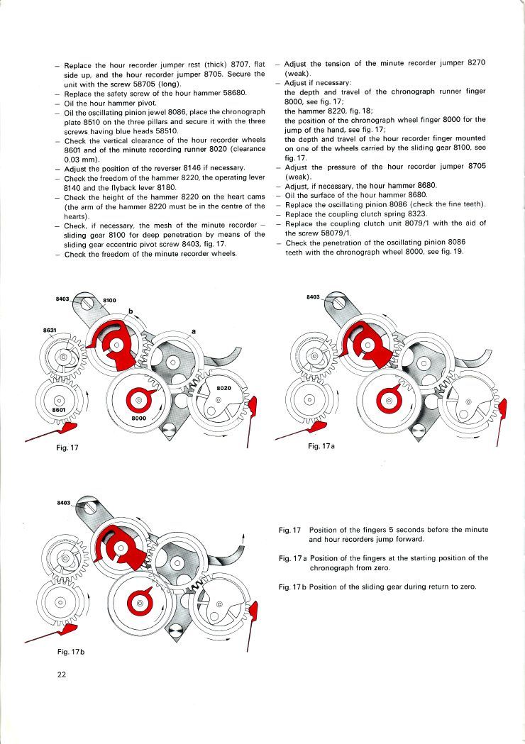
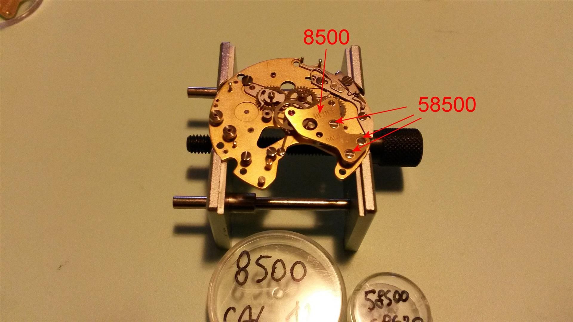
11) Replace the chronograph bridge 8500 with its three screws 58500 (bear in mind that, at the end of the reassembling, we will have to dismount it again to add a lever, so don’t tighten the screws):
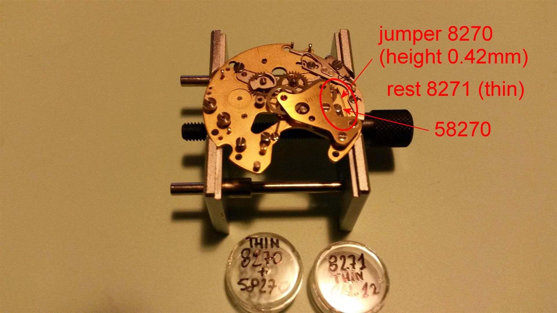
12) Position the minute recorder jumper spring rest 8271 (is the thinner one) and the minute recorder jumper 8270, then fix them together with the screw 58270 (sorry for the ugly image, is partially hidden):
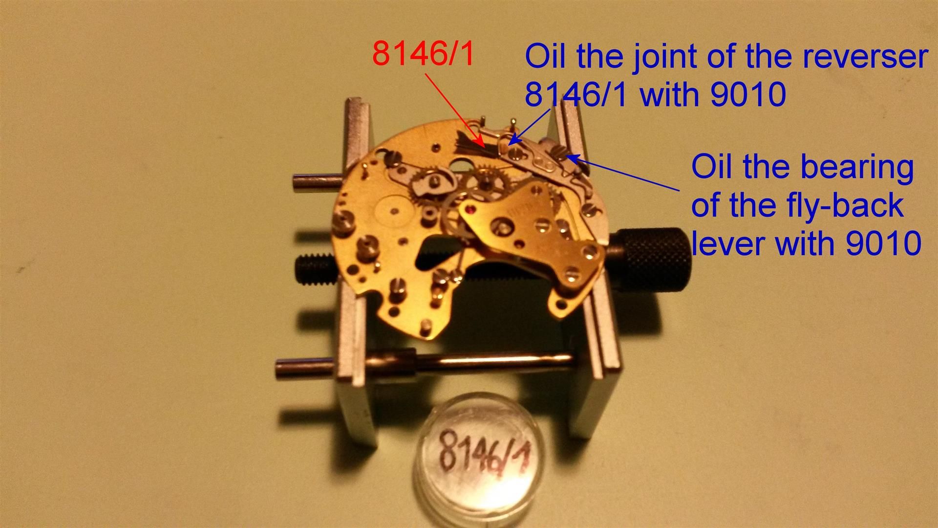
13) Replace the reverser 8146/1, then oil with 9010 the joint of the reverser (it partially rotates during the start/stop pusher action so needs low friction) and oil the bearing of the fly-back lever 8180 with 9010 and the contact point with the spring 8335/8340:
14) Replace the hammer cam jumper 8356 fixing it with its screw 58356, then grease with KT22 the operating lever 8140 beneath each of its screws 58140:
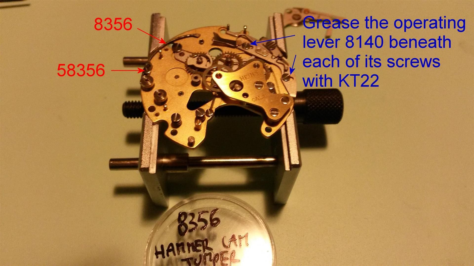
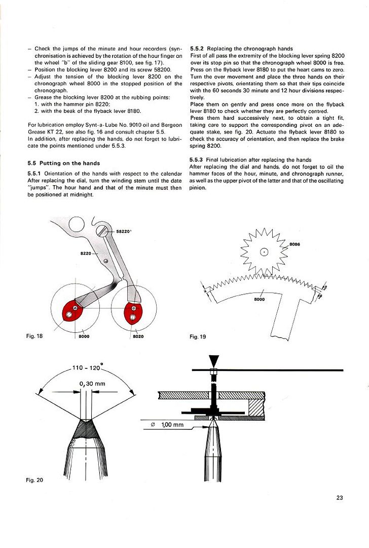
15) Secure the hammer 8220 using the screw 58220 (gently open the hammer cam jumper 8356 during the operation), then oil the bearing of the hammer 8220 (probably is better to put a drop of oil around the bearing before put the screw in order not to spread the oil around the hammer screw hole).
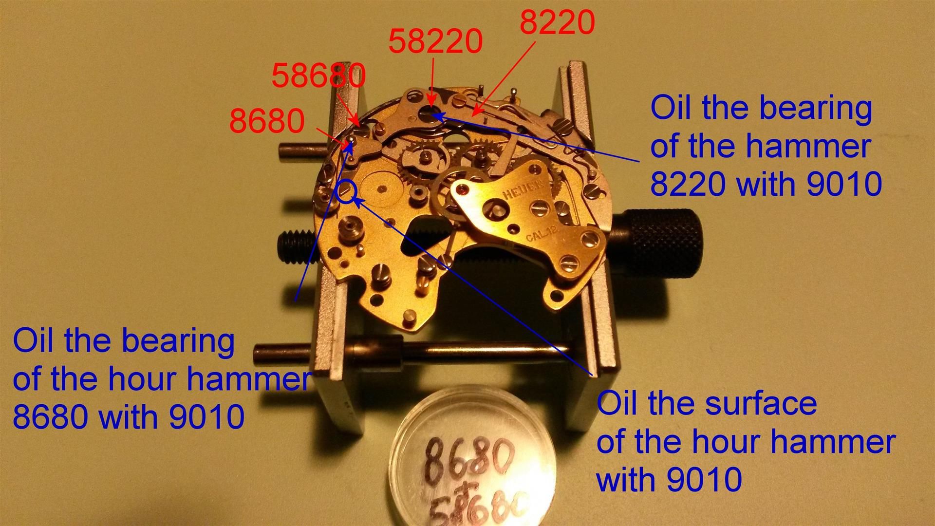
Then replace the hour hammer 8680 (the one which resets the hour recorder small hand) and its safety screw 58680, leaving its spring free (I prefer instead to immediately tension the spring but is essential NOT to move the 8220 from the open position in order to leave the hour hammer open), then oil its pivot (like above, if you have the parts dismounted probably is better to put a drop of oil on the pivot before fitting the part).
Oil also the surface of the hammer to avoid friction when beating on the heart cam of the wheel 8631 (see further):
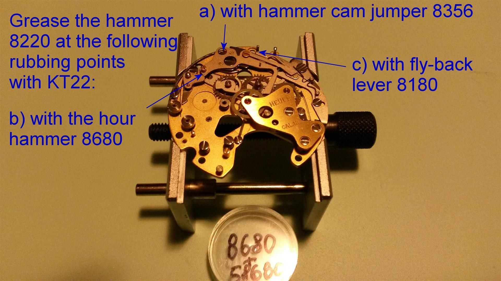
16) Grease with KT22 the hammer 8220 at the following rubbing points:
- with the hammer cam jumper 8356 (this is essential to have a poor friction = smooth movement of the pushers when start / stop / reset, you will have to move the hammer 8220 to reach all the grooves to be greased and this is the reason why is better to position the spring of the hour hammer 8680 after this step);
- with the hour hammer 8680;
- with the fly-back lever 8180;
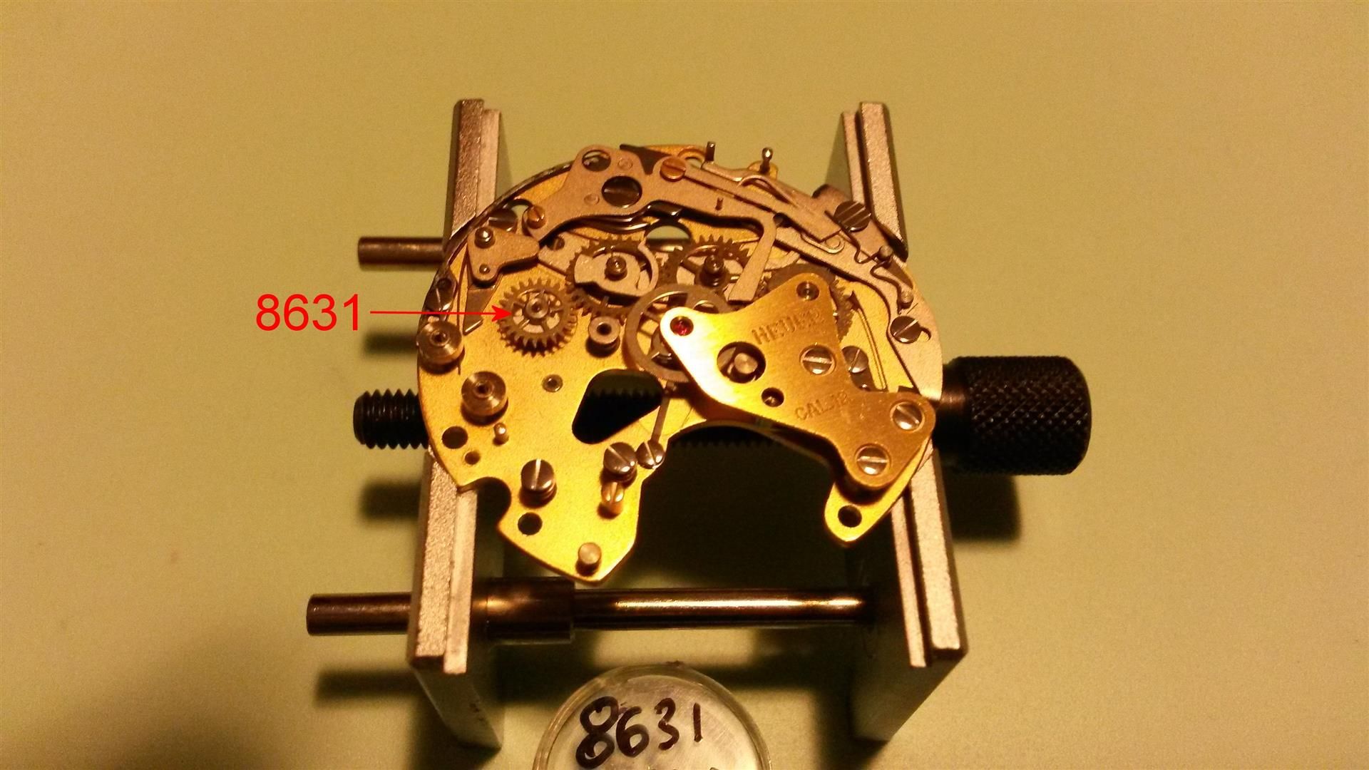
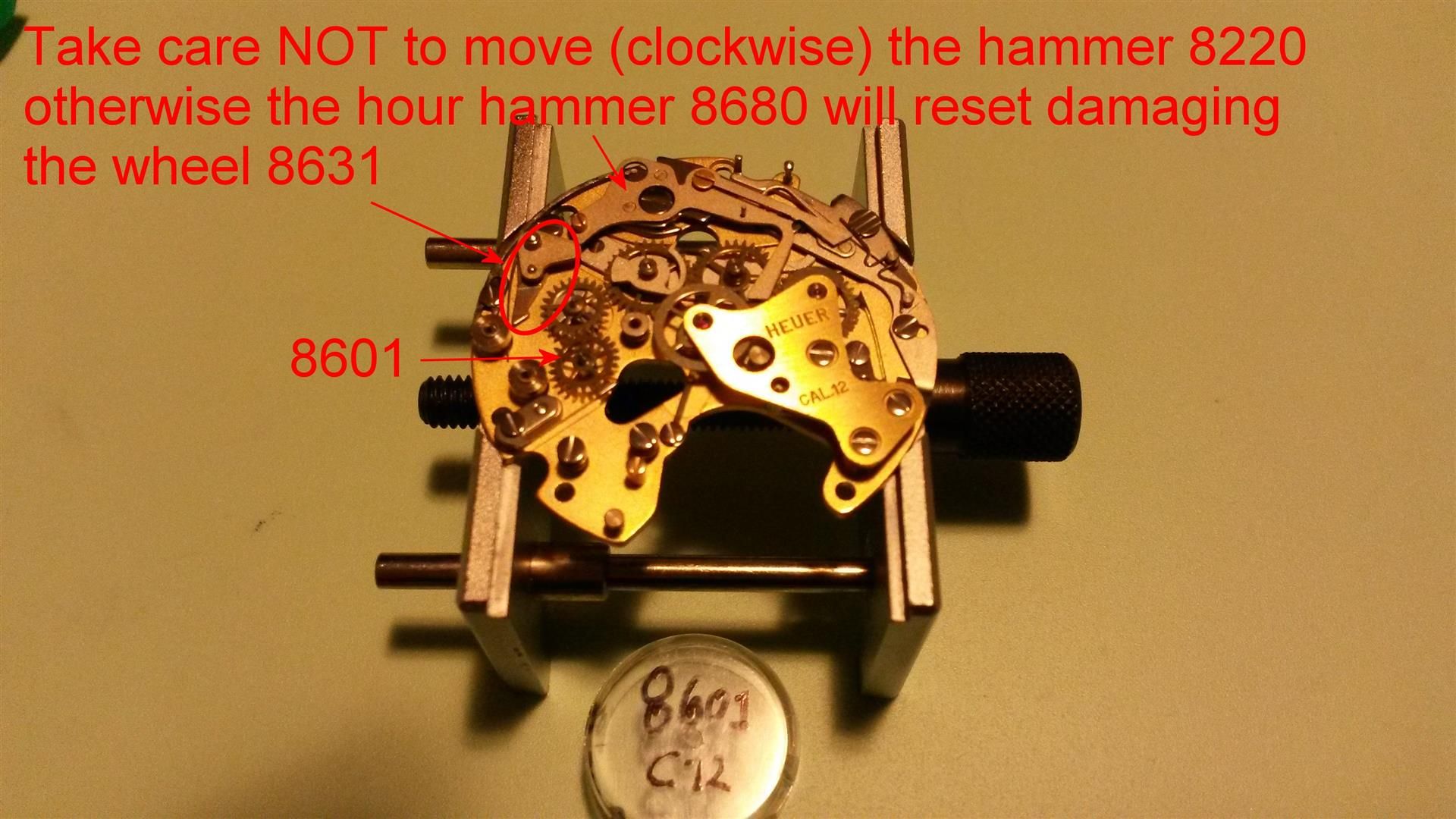
17) Replace the connecting wheel for hour recorder 8631 (beware: NOT to move the hammer 8220 for obvious reasons):
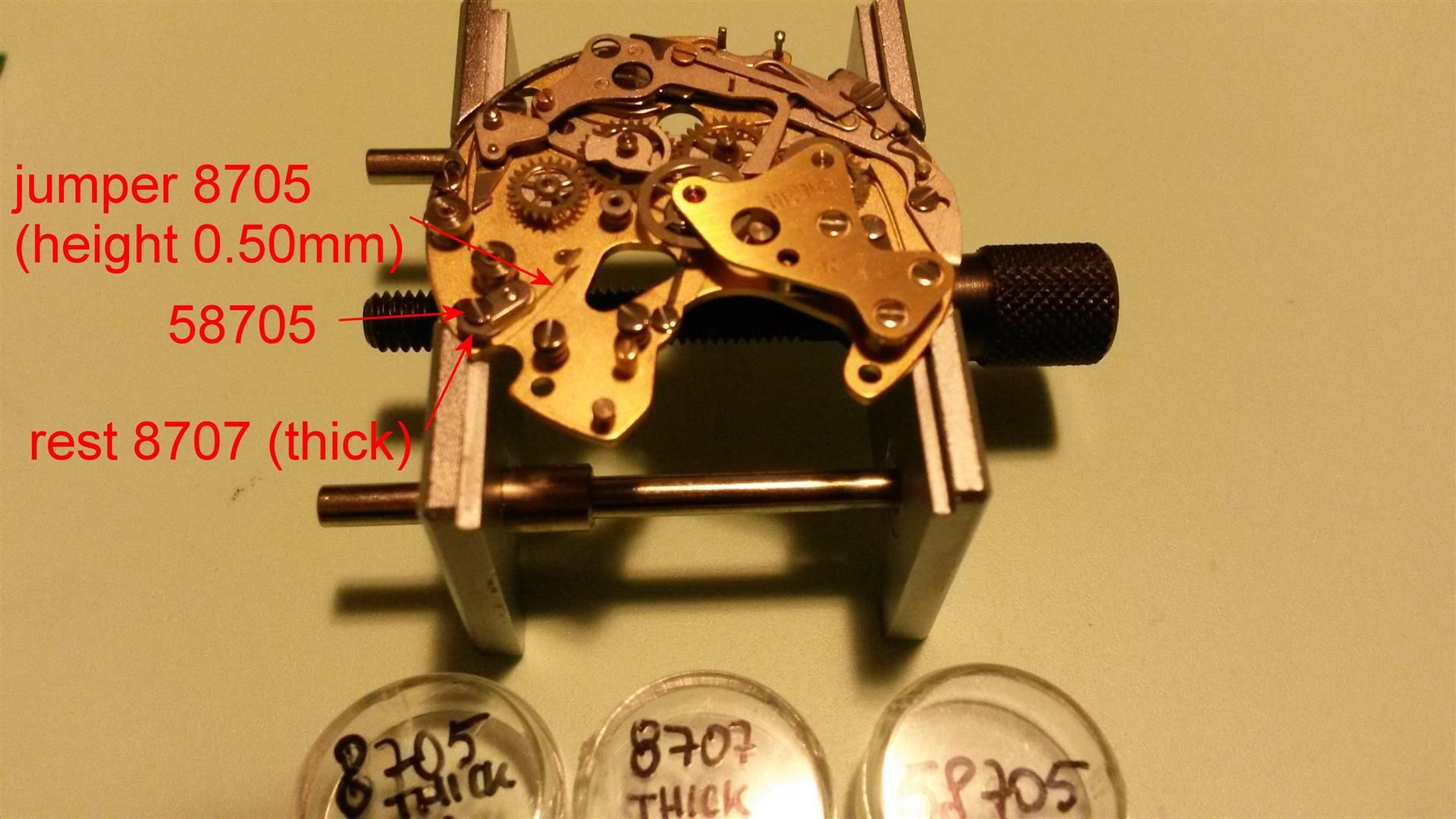
18) Replace the hour recorder jumper rest (is the thicker one) 8707, flat side up, and the hour recorder jumper 8705 (is the thicker one too, this is 0.50mm height while the 8270 is 0.42mm) and secure them with the screw 58705. I prefer to replace the jumper 8707 BEFORE replacing its wheel while the manual suggests the opposite, for me is easier as the jumper will help the hour recorder wheel to stay in place pressed towards the 8631 and thus facilitating the mounting of the bridge):
19) Replace the hour recorder wheel 8601. If not already done this is the moment to put in place the spring of the hour hammer:
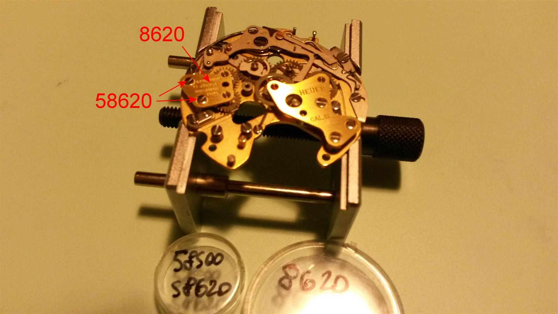
20) Replace the hour recorder bridge 8620 and its two screws 58620:
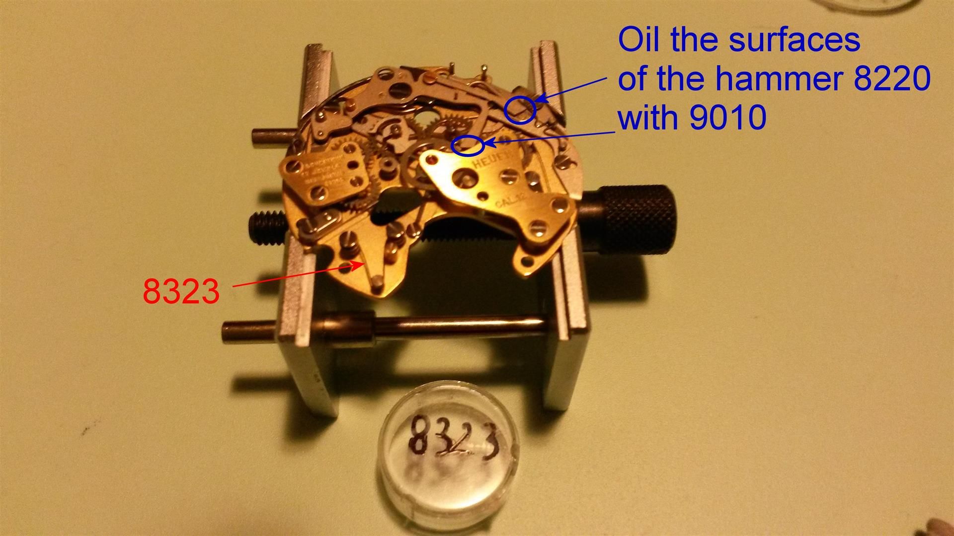
21) Replace the coupling clutch spring (for oscillating pinion) 8323, then oil both the surfaces of the hammer 8220 (essential to avoid rubbing when the hammer beats on the heart cams of the wheels 8000 and 8020):
22) Replace the coupling clutch unit 8079/1 with its fixing screw 58079/1 and check that it moves freely stopping between the two other screws 58079/1 (the first ones replaced at the beginning of the reassembling procedure):

23) Now you can position the spring 8323 on the pin located on the bottom side of the coupling clutch 8079/1 in order to tension the coupling clutch in the rest position (when the chronograph is disengaged the oscillating pinion 8086 spins freely not engaging the chronograph central runner 8000, the travel done from the oscillating pinion - that is its penetration into the teeth of the 8000 wheel - is regulated by the golden eccentric located below one of the screws 58079/1).
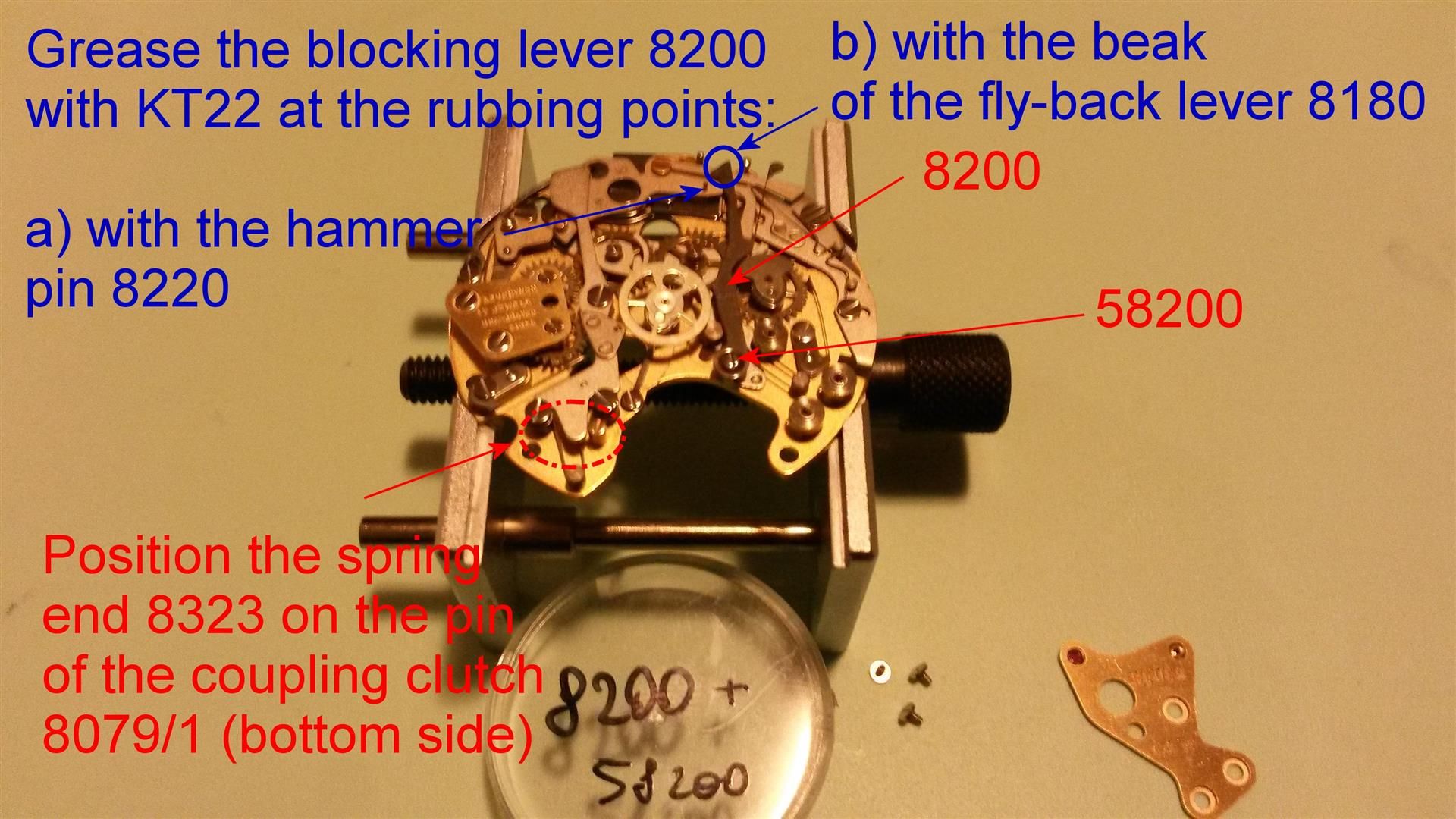
Then remove the chronograph bridge 8500 and position the blocking lever 8200 and its screw 58200, then replace the bridge 8500 and secure firmly its three screws.
The blocking lever 8200 has the function to block the chronograph wheel 8000 (and thus the central second hand) during the stop phase and when the chrono is disengaged, but must free the wheel 8000 during the chrono running and reset phases, so verify the tension of the blocking lever 8200 in the stopped position of the chronograph passing the extremity of the blocking lever spring over its stop pin. Bear in mind that:
- an excessive tension can damage the fine teeth of the chronograph runner 8000;
- never turn by hand the chronograph runner 8000 while the blocking lever is in its stop position (that is pressed) for the reason above.
Lastly grease the blocking lever 8200 at the rubbing points:
- with the hammer pin 8220;
- with the beak of the fly-back lever 8180.
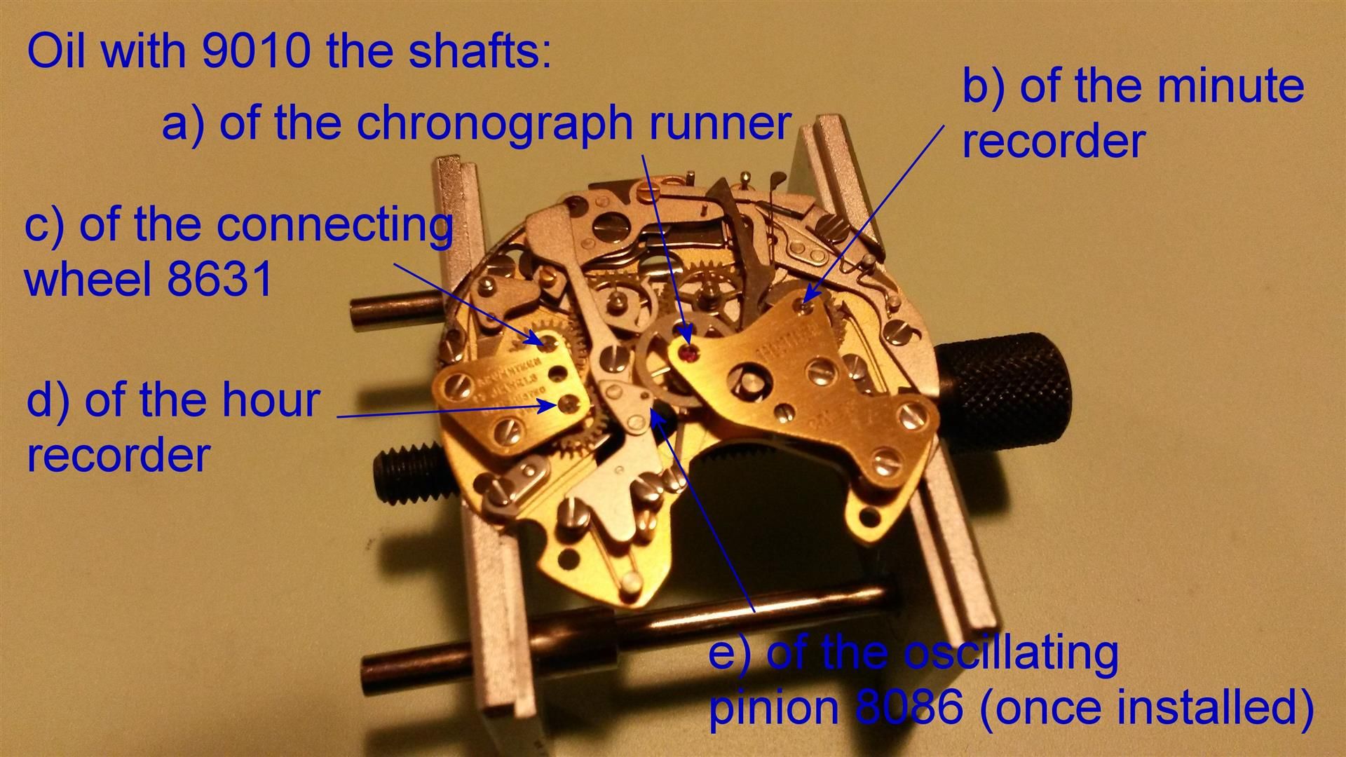
24) Now the chronograph module is completely assembled, so you can oil with 9010 the upper pivots of the wheels 8000 (chrono seconds), 8020 (minute recorder), 8601 (hour recorder), 8631 (connecting wheel).
After having replaced the chronograph module on the basic movement (don’t forget to oil the lower jewel of the oscillating pinion 8086 with oil 9010 and replace the oscillating pinion too) and secured it with the three blue screws 58510 don’t forget to oil also the upper bearing of the oscillating pinion (very important: the oscillating pinion always spins despite the chronograph is engaged or not, so if not lubricated can wear out prematurely and this is a really expensive and hard-to-find spare part nowadays):
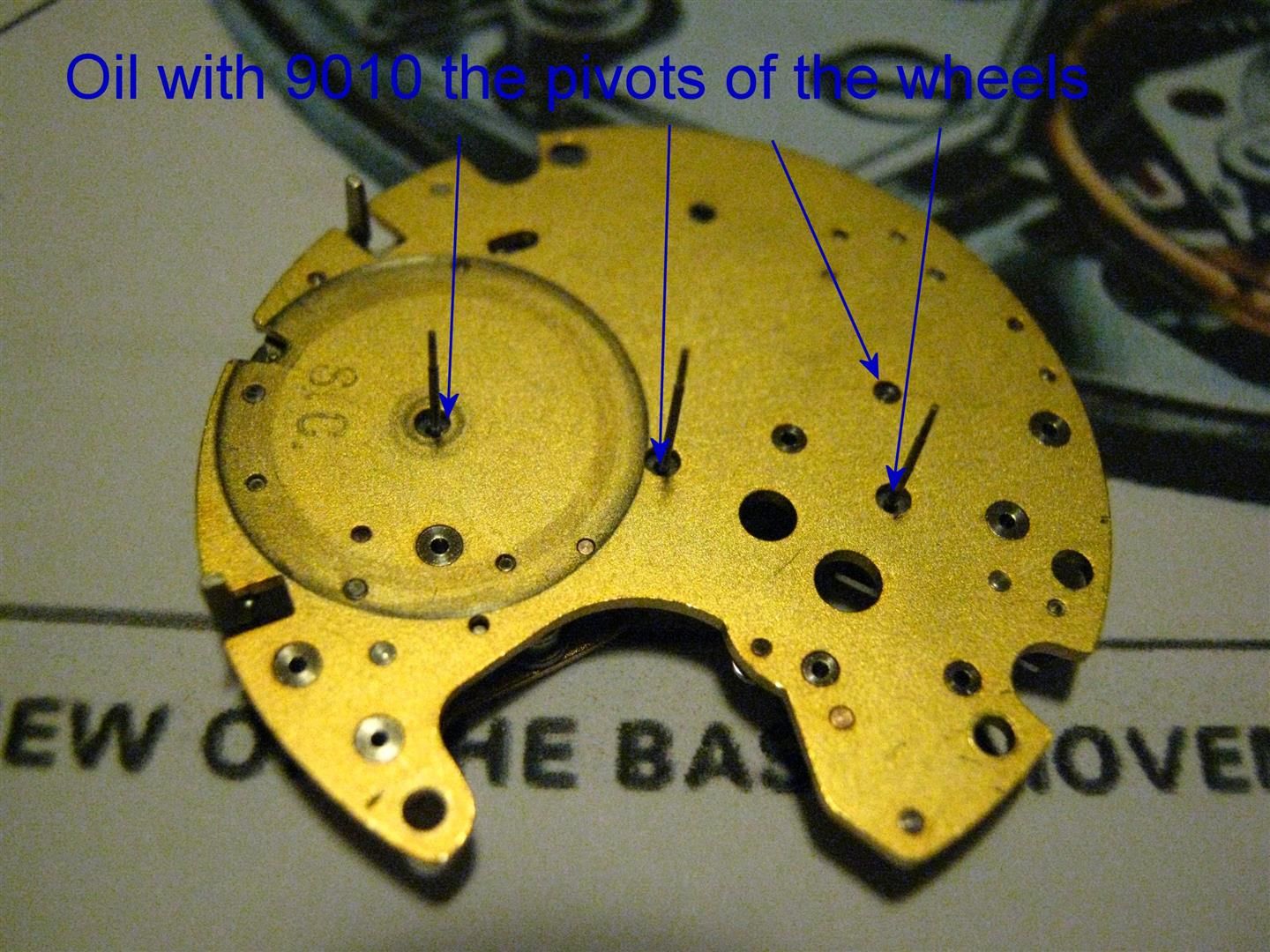
25) Even if the manual doesn’t suggest to oil any point on the lower side of the chronograph module I usually put a tiny drop of 9010 also on the following points, even if this is less important because the three shafts of the three chrono wheels will pass through the basic movement (the 8020 through the microrotor hollow arbor, the 8000 through the center pipe 163/1 where the minute hand spins) so there will be other rubbing points to be lubricated on the basic movement too.
Hope you enjoyed if you arrived until here :-)
Gianluca
| Chronocentric and zOwie site design and contents (c) Copyright 1998-2005, Derek Ziglar; Copyright 2005-2008, Jeffrey M. Stein. All rights reserved. Use of this web site constitutes acceptance of the terms of use. | CONTACT | TERMS OF USE | TRANSLATE |